Frame Analysis Project
Overview
Frame construction is used throughout the aerospace industry in the creation of welded steel-tube fuselages, piston-engine motor mounts, ribs, and landing gear. In this activity I design a frame assembly for a motor mount structure for a Lycoming O-300 to be installed in a light aircraft.
Equipment
Computer with Autodesk® Inventor® installed and access to the internet.
Procedure
The frame must meet the constraints shown below.
1. The large plate represents the aircraft firewall as shown in the image below. This must be grounded as the stable part of the frame. Use fixed constraints on the seven firewall to structural member attachment point.
2. The structure will support one Lycoming O-300 engine (250 lb) attached at the three points indicated.
3. The structure will be loaded with negative 3 G and positive 6 G which is simulated by exaggerated engine weight.
4. The structural members will be 1 ½ in. ANSI pipe.

I calculated the forces that must be simulated with the positive and negative G loads. I labeled the frames below with the forces that will be modeled for each loading condition. I also labeled the structural members below as compression or tension. I predict where the critical point will be for each loading condition.
Positive 6 G's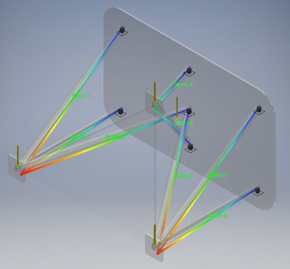
|
Negative 3 G's
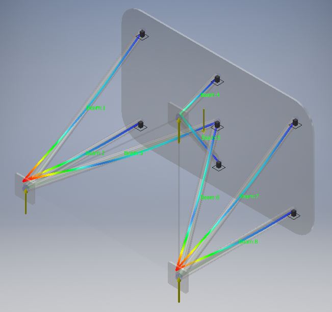
|
Design
I decided to use Autodesk Inventor to create a model of my frame design.

Frame Analysis


Design Benefits
My design is made of titanium which is very strong so the engine mount will not break easily.
Conclusion
1. The frame analysis was a more accurate representation of what would really happen to the engine mount if someone was to put it under the presented conditions.
2. Temperature of the engine, pressure, weight of engine.
2. Temperature of the engine, pressure, weight of engine.
